I’ve published a utility for calculating the cut depth and cut width when using V-shaped bits to engrave a PCB.
The live-action implementation can be found here.

I’ve published a utility for calculating the cut depth and cut width when using V-shaped bits to engrave a PCB.
The live-action implementation can be found here.
I just finished a program and a library to use an XBox 360 Chatpad as a Linux keyboard using the input sub-system. This means it acts exactly like a native keyboard and works with even framebuffer terminals. I’ve used it on my laptop with a USB serial adapter and on a Raspberry Pi.
Usage and more details can be found on the Github page here: https://github.com/timstableford/chatpad-linux
Just as a warning for some reason one of my USB serial adapters didn’t work properly with the keyboard and I had to try another.
Raspberry Pi Zero’s come equipped with a USB OTG port which means they can act as a USB client, such as in this case becoming a network adapter. There are quite a few articles on configuring the Pi to do this but most of them are based on Raspbian Jessie rather than Raspbian Stretch. There’s only a small difference but it’s not well documented really.
This guide will cover:
This guide also assumes some familiarity with the Linux console and Ubuntu.
This is a simple enough step but somewhat depends on the host machine and your preferences. I used the minimal Raspbian Stretch image from here. You might choose to use the full version but keep in mind this guide will only work with a version of Raspbian Stretch.
Unzip the downloaded image with your archiver GUI or…
(cd ~/Downloads && unzip *-raspbian*.zip)
Flash the image to your SD card (beware of DD the data destroyer when using this):
sudo dd if=$(ls ~/Downloads/*raspbian-stretch-*.img) of=/dev/mmcblk0
All done, now make sure to type sync in your terminal then remove the SD card and put it back in again.
With your GUI file manager click on boot and rootfs to mount them if they haven’t been already. Then open up cmdline.txt in the boot partition and add modules-load=dwc2,g_ether at the end of the line after rootwait.
Now open up config.txt in the boot partition and add dtoverlay=dwc2 to the end of the file.
Make sure those are saved and then we’ll do the complicated part.
This next part is where it differs between Jessie and Stretch in newer releases you need to modify /etc/dhcpcd.conf and in older releases /etc/network/interfaces, this will only cover the former.
So next we need to append the following network configuration to /etc/dhcpcd.conf:
interface usb0
static ip_address=192.168.137.2
static routers=192.168.137.1
The reason the above chooses 192.168.137.0 is because that’s the default IP range used by Windows Internet Connection Sharing, making this also compatible with Windows.
This is a bit tricky because only root can write the filesystem, so to get round this, run the following:
export INTERFACES=/media/${USER}/rootfs/etc/dhcpcd.conf
cat << EOF | sudo tee --append ${INTERFACES}
interface usb0
static ip_address=192.168.137.2
static routers=192.168.137.1
EOF
Lastly eject the rootfs and boot partitions using your file manager, and then the SD card is all setup.
First we need to configure the network with a static IP.
IPv4 settings.Automatic (DHCP) to Manual.192.168.137.1 and the subnet 255.255.255.0 and leave the gateway blank.At this point connect the Pi to the computer via the USB OTG port and wait patiently for it to boot up, when it has it should automatically connect to the PiStatic network. At this point you should be able to ping/ssh into the Pi using:
ssh pi@192.168.137.2
(the default password is raspberry)
Now the last thing to do is enable forwarding your computers internet connection. In the console run ifconfig to find out the name of your internet connected interface it may be eth0 or something more obscure like enp0s31f6.
Then run the following commands (replace eth0 with your network interface):
sudo sysctl net.ipv4.ip_forward=1
sudo iptables -A FORWARD -o eth0 -j ACCEPT
sudo iptables -A FORWARD -m state --state ESTABLISHED,RELATED -i eth0 -j ACCEPT
sudo iptables -t nat -A POSTROUTING -o eth0 -j MASQUERADE
The forwarding will not persist across reboots so keep a note of those commands, it’s possible to make it permanent but it is a security vulnerability.
You should now be able to SSH into the Pi and ping external sites such as google.co.uk.
Interfacing with a keypad takes a lot of IO doesn’t it? There isn’t really space to do much else on an Arduino of ESP8266 after having 7 or 8 pins taken for a keypad. Luckily there’s a cheap solution for this one, using an I2C I/O expander. In this case the PCF8574AP· The ‘A’ being the alternate address version.
The first part to do, if it’s not supplied with your keypad is to figure out which pins connect to which keys. This is nearly always done in a grid configuration with rows and columns. To read this configuration you set all the pins to high/input-pullup except for a single column and then see which row is pulled low.
To figure out my keypad layout I attached a multi-meter to each of the pins on the keypad while in buzzer mode and noted which pins correlated to which button. Then it’s just a matter of finding the common theme and making your grid as below.
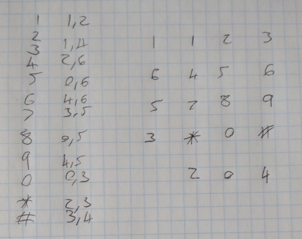
Most keypads don’t tend to have such a complicated pin-out and will often group the columns together.
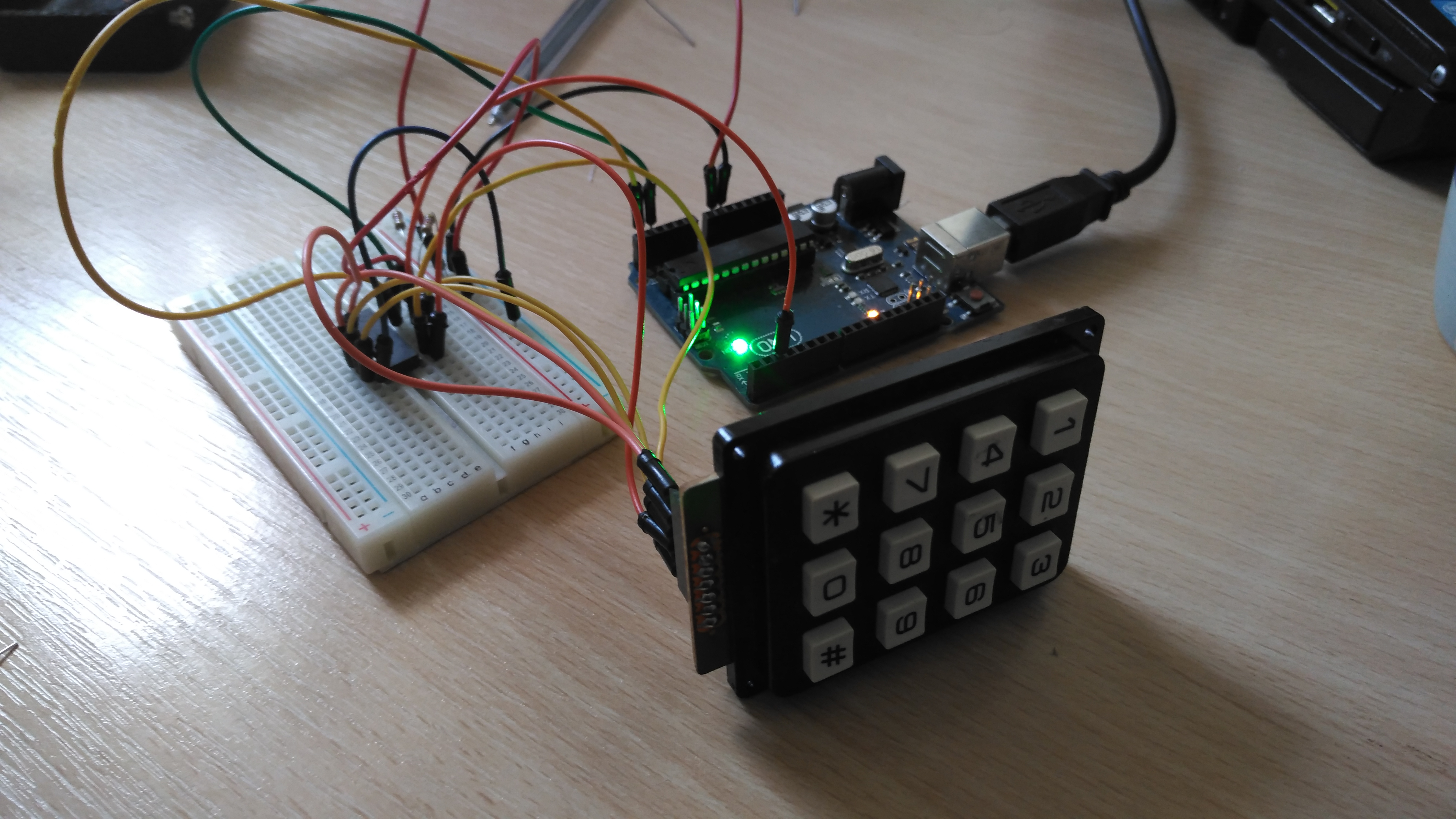
Next step is to wire it all together, for this you will need:
Then wire it up to the PCF8574 as follows:
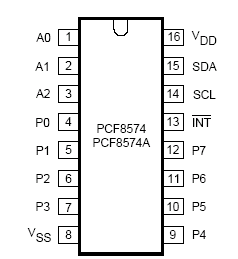
| PCF8574 Pin | Arduino Pin | Keypad Pin |
|---|---|---|
| SDA/15 | A4 (and 5V through 4.7k resistor) | |
| SCL/14 | A5 (and 5V through 4.7k resistor) | |
| INT/13 | 2 | |
| VDD/16 | 5V | |
| VSS/8 | GND | |
| INT/13 | 2 | |
| P[0..6] | [0..6] |
After that it should like something like the following:
Then the last step, the code:
#include <Arduino.h>
#include <Wire.h>

// This is the address for the 'A' variant with all address pins not connected (high).
// Check the datasheet for other addresses. http://www.ti.com/lit/ml/scyb031/scyb031.pdf
#define PCF_ADDR (0x27)
#define INTERRUPT_PIN (2)
#define DEBOUNCE_DELAY (200) // milliseconds

bool keyPressed = false;
int32_t lastPress = 0;

// Interrupt called when the PCF interrupt is fired.
void keypress() {
  if (millis() - lastPress > DEBOUNCE_DELAY) {
    keyPressed = true;
  }
}

// The pins for each of the columns in the matrix below. P7 to P0.
uint8_t kColumns[] = { B00000100, B00000001, B00010000 };
uint8_t kRows[] = { B00000010, B01000000, B00100000, B00001000 };
char kMap[][3] = {
  { '1', '2', '3'},
  { '4', '5', '6'},
  { '7', '8', '9'},
  { '*', '0', '#'}
};
// This is the value which is sent to the chip to listen for all
// key presses without checking each column.
uint8_t intMask = 0;

// The PCF chip only has one I2C address, writing a byte to it sets the state of the
// outputs. If 1 is written then they're pulled up with a weak resistor, if 0
// is written then a transistor strongly pulls it down. This means if connecting an LED
// it's best to have the chip as the ground terminal.
// If passing a byte value to this, eg B11111111 the left most bit is P7, the right
// most P0.
void write8(uint8_t val) {
  int error = 0;
  // This will block indefinitely until it works. This would be better done with a
  // timeout, but this is simpler. If the I2C bus isn't noisy then this isn't necessary.
  do {
    Wire.beginTransmission(PCF_ADDR);
    Wire.write(val);
    error = Wire.endTransmission();
  } while(error);
}

uint8_t read8() {
  uint8_t read = 0;
  do {
    read = Wire.requestFrom(PCF_ADDR, 1);
    if (read == 1) {
      return Wire.read();
    }
  } while (read != 1);
}

void setup() {
  Serial.begin(115200);

  Wire.begin();
  // When a pin state changed on the PCF it pulls its interrupt pin low.
  // It's an open drain so an input pullup is necessary.
  pinMode(INTERRUPT_PIN, INPUT_PULLUP);
  attachInterrupt(digitalPinToInterrupt(INTERRUPT_PIN), keypress, FALLING);

  // Calculate the interrupt mask described above.
  for (uint8_t c = 0; c < sizeof(kColumns) / sizeof(uint8_t); c++) {
    intMask |= kColumns;
  }
  intMask = ~intMask;
  write8(intMask);
}

// This goes through each column and checks to see if a row is pulled low.
char getKey() {
  for (uint8_t c = 0; c < sizeof(kColumns) / sizeof(uint8_t); c++) {
    // Write everything high except the current column, pull that low.
    write8(~kColumns);
    uint8_t val = read8();
    // Check if any of the columns have been pulled low.
    for (uint8_t r = 0; r < sizeof(kRows) / sizeof(uint8_t); r++) {
      if (~val & kRows[r]) {
        return kMap[r];
      }
    }
  }
  return '\0';
}

void loop() {
  if (keyPressed) {
    char key = getKey();
    // Key may not be read correctly when the key is released so check the value.
    if (key != '\0') {
      Serial.println(key);
      lastPress = millis();
    }
    keyPressed = false;
  }
  // After getKey this needs to be called to reset the pins to input pullups.
  write8(intMask);
}
When uploaded and everything wired together the sketch will output the pressed key to the serial console.
Edited 3/12/2018: Updated CPP code to compile properly.
Many times have I found myself needing to communicate with an Arduino over serial, often wanting to send complex data types. Often too simpler types such as a 4 byte int. Then there is the code necessary to figure out when you’ve started sending that int and what to do with it. Then what if you want to send more than one int?
I’ve implemented an asynchronous RPC library for Arduino, and C++/Java on PC. It allows invoking remote methods and passing complex data types over serial. I’m sure has been done before, this library though attempts to find a middle ground between minimal and usable. There are limitations, such as a lack of return types, limitations on packet sizes (65535) and string sizes (255), it should suite most purposes though.
For running the examples I’m going to assume the host is a Linux environment (tested on Ubuntu 16.04).
First download and install the Arduino library.
mkdir -p ~/Arduino/libraries
git clone https://github.com/timstableford/LRPC-Arduino-C ~/Arduino/libraries/RPC
Then you’ll need to restart the Arduino IDE. Following that, in the Arduino IDE under File -> Examples -> Examples from Custom Libraries -> RPC you will find rpc_ping. It will give a few compiler warnings about shifting bytes, that’s expected. Upload it and you’ll be good to go.
Next install and run the Java example that matches the sketch.
cd ~/Documents
git clone https://github.com/timstableford/LRPC-Java
cd LRPC-Java
./gradlew runPing
On my Github I’ve put up the Arduino library, which includes a ping pong example. This sketch waits for a ping RPC call from the server (Java) and responds with a pong RPC call. The following paragraphs will do a breakdown of some important points in the code.
The serialReader and serialWriter functions are simple wrappers around Serial read and write, these are here so the library could be used over alternate communication mechanisms, such as I2C.
The next item of importance is the RPC function declaration table.
RPC::RPCContainer rpcs[] = {
  { 1, rpcPing, NULL },
  { 2, rpcPong, NULL }
};
This lists RPC function ID’s, pointers to the functions, and some user data you may wish to pass to the function, in this case it’s NULL because we don’t want to. Inside these functions is a reference to an Object, this contains various functions for getting and setting data. In RPC callbacks, the 0th item is the function ID and any items after are user data. In this case the 1st item is the time in milliseconds as an int64.
There’s a few different ways to respond to RPC calls if you dig deep enough you can construct Objects manually. However, this library includes a wrapper similar to printf that supports many data types. A list of supported data types is near the end of this post.
An example is:
rpc.call(2, "m", (int64_t)millis() + time_offset);
The first item is the function ID to call. The second item is like the printf format specifier. In this example though all types are dictated by a single character for ease of parsing. “m” is the type specifier for an int64. Following the format specifier is a list of data items to send.
Skipping over the constructors because they’re mostly the same in all sketches. You may vary the buffer size, depending on the size of the RPC calls you’re making to the Arduino sketch.
The final important part to making it all work is
while(parser.parse() >= 0);
Each call to parser.parse reads one byte. I recommend doing it like this, it will return a number less than 0 when there are no bytes left for it to read. If you have other time sensitive operations though, it would be possible to limit the number of bytes to read in a single loop.
I’ve also put a Java example on Github that connects over serial to the Ardunio sketch and sends regular ping commands. This is a little more verbose than the Arduino sketch because it contains multiple threads. The general flow is the same though. The biggest difference is how RPC calls are made.
rpc.call(PONG_FID, new LSerializer(LObjects.Int(LType.INT64, System.currentTimeMillis())));
An LSerializer object is the equivalent of an Object class in the Arduino sketch, it handles most of the serialising and de-serialising. However, type specific code is handled in the LObjects class. This is a far easier way to add additional types, but adds a lot of overhead. So interfaces are avoided in the C++/Arduino implementation.
The RPC protocol has two parts. A low-level packet layer called Stream Parser which has a header containing information about how much data is to be received. It buffers all that data and then passes it along to a registered callback dependant on the packet type specified in the header. For instance, RPC is 8.
The other portion of the called called RPC/Object takes a buffer and parses it into a more accessible form, avoiding data duplication where possible. The Object class serialises and de-serialises data, whereas the RPC class routes incoming RPC calls to the correct functions, and in the C++ implementation provides a wrapper around creating objects using a printf like format.
A stream parser packet consists of 6 bytes, all data types are in network byte order. The first two bytes are a uint16 containing the packet type, the second two bytes are another uint16 dictating the size of the packet to be received, and the final two bytes are a 32-bit crc of the first 4 bytes. This means a header can be picked up at any point in a stream. After reading the header, the stream parser attempts to read all of the data bytes. If successful it gets passed along through a callback registered to the type.
| Name | Size (bytes) | Type | Description |
|---|---|---|---|
| type | 2 | uint16 | The type of the incoming packet. |
| size | 2 | uint16 | The size of the data to receive after the header. |
| crc | 2 | uint16 | A CRC 32 of the type and size. |
The Object class is a way to transfer different data types while preserving what sort they are and providing a wrapper to easily set and get items from a buffer. The first piece of data in a serialised Object is an unsigned byte which specifies the number of items to be transmitted. For instance two ints would be ‘2’, one string would be ‘1’. (Not encoded as characters.) After that, there’s a 1 byte type specifier for each piece of data to be transmitted. For data types with fixes size, that’s all. For data types of variable size such as strings there’s an additional table after the type specifier that specifies sizes. Currently there’s a maximum string length of 255. After that is just plane data, in network byte order where applicable.
| Name | Size (bytes) | Type | Description |
|---|---|---|---|
| item_count | 1 | uint8 | A count of the data items in the object. |
| data_type | 1 (per data item) | uint8 | Type specifier's for each data item. |
| string_size | 1 (per array/string item) [0 if no strings] | uint8 | Specifies the length of a string/array element. |
| data | variable | variable | Serialized data, ints are in network byte order, strings are raw. |
RPC packets are an Object class. The first piece of data is a uint16 to specify the RPC function ID. The rest is the encoded data.
The table below lists the type specifiers for rpc.call:
| Character | Data type |
|---|---|
| s | String |
| c | int8 |
| C | uint8 |
| d | int16 |
| D | uint16 |
| l | int32 |
| L | uint32 |
| m | int64 |
| M | uint64 |
| f | float |