Interfacing with a keypad takes a lot of IO doesn’t it? There isn’t really space to do much else on an Arduino of ESP8266 after having 7 or 8 pins taken for a keypad. Luckily there’s a cheap solution for this one, using an I2C I/O expander. In this case the PCF8574AP· The ‘A’ being the alternate address version.
The first part to do, if it’s not supplied with your keypad is to figure out which pins connect to which keys. This is nearly always done in a grid configuration with rows and columns. To read this configuration you set all the pins to high/input-pullup except for a single column and then see which row is pulled low.
To figure out my keypad layout I attached a multi-meter to each of the pins on the keypad while in buzzer mode and noted which pins correlated to which button. Then it’s just a matter of finding the common theme and making your grid as below.
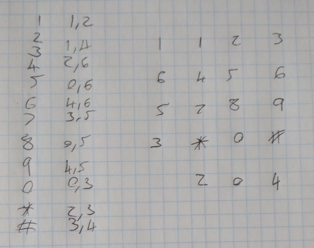
Most keypads don’t tend to have such a complicated pin-out and will often group the columns together.
Next step is to wire it all together, for this you will need:
- 2x 4.7kOhm Resistors
- Arduino Uno/Due
- Keypad
- PCF8574
- Misc cables
- (Optional) Breadboard
Then wire it up to the PCF8574 as follows:
| PCF8574 Pin | Arduino Pin | Keypad Pin |
|---|---|---|
| SDA/15 | A4 (and 5V through 4.7k resistor) | |
| SCL/14 | A5 (and 5V through 4.7k resistor) | |
| INT/13 | 2 | |
| VDD/16 | 5V | |
| VSS/8 | GND | |
| INT/13 | 2 | |
| P[0..6] | [0..6] |
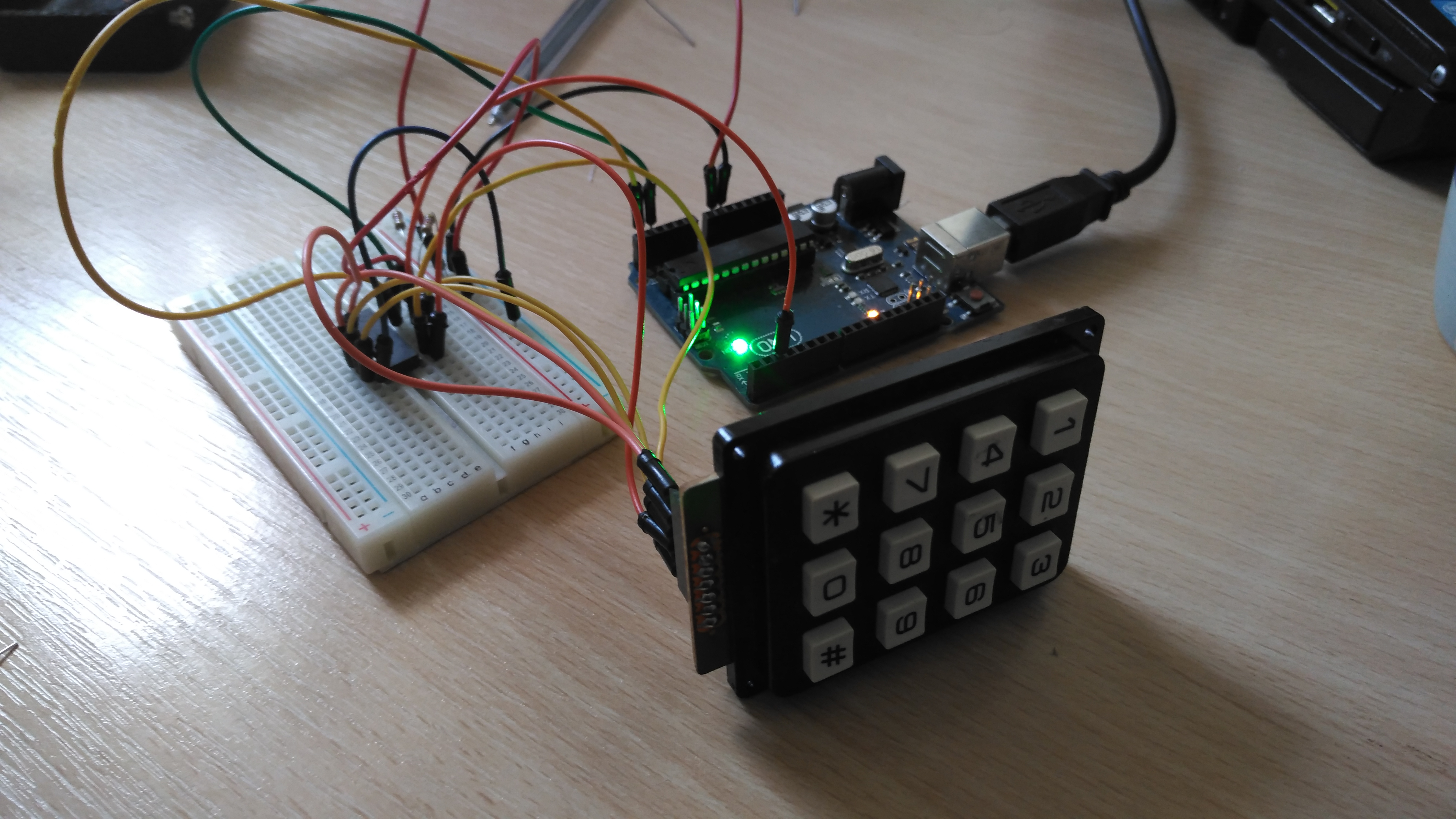
After that it should like something like the following:
Then the last step, the code:
#include <Arduino.h>
#include <Wire.h>

// This is the address for the 'A' variant with all address pins not connected (high).
// Check the datasheet for other addresses. http://www.ti.com/lit/ml/scyb031/scyb031.pdf
#define PCF_ADDR (0x27)
#define INTERRUPT_PIN (2)
#define DEBOUNCE_DELAY (200) // milliseconds

bool keyPressed = false;
int32_t lastPress = 0;

// Interrupt called when the PCF interrupt is fired.
void keypress() {
  if (millis() - lastPress > DEBOUNCE_DELAY) {
    keyPressed = true;
  }
}

// The pins for each of the columns in the matrix below. P7 to P0.
uint8_t kColumns[] = { B00000100, B00000001, B00010000 };
uint8_t kRows[] = { B00000010, B01000000, B00100000, B00001000 };
char kMap[][3] = {
  { '1', '2', '3'},
  { '4', '5', '6'},
  { '7', '8', '9'},
  { '*', '0', '#'}
};
// This is the value which is sent to the chip to listen for all
// key presses without checking each column.
uint8_t intMask = 0;

// The PCF chip only has one I2C address, writing a byte to it sets the state of the
// outputs. If 1 is written then they're pulled up with a weak resistor, if 0
// is written then a transistor strongly pulls it down. This means if connecting an LED
// it's best to have the chip as the ground terminal.
// If passing a byte value to this, eg B11111111 the left most bit is P7, the right
// most P0.
void write8(uint8_t val) {
  int error = 0;
  // This will block indefinitely until it works. This would be better done with a
  // timeout, but this is simpler. If the I2C bus isn't noisy then this isn't necessary.
  do {
    Wire.beginTransmission(PCF_ADDR);
    Wire.write(val);
    error = Wire.endTransmission();
  } while(error);
}

uint8_t read8() {
  uint8_t read = 0;
  do {
    read = Wire.requestFrom(PCF_ADDR, 1);
    if (read == 1) {
      return Wire.read();
    }
  } while (read != 1);
}

void setup() {
  Serial.begin(115200);

  Wire.begin();
  // When a pin state changed on the PCF it pulls its interrupt pin low.
  // It's an open drain so an input pullup is necessary.
  pinMode(INTERRUPT_PIN, INPUT_PULLUP);
  attachInterrupt(digitalPinToInterrupt(INTERRUPT_PIN), keypress, FALLING);

  // Calculate the interrupt mask described above.
  for (uint8_t c = 0; c < sizeof(kColumns) / sizeof(uint8_t); c++) {
    intMask |= kColumns;
  }
  intMask = ~intMask;
  write8(intMask);
}

// This goes through each column and checks to see if a row is pulled low.
char getKey() {
  for (uint8_t c = 0; c < sizeof(kColumns) / sizeof(uint8_t); c++) {
    // Write everything high except the current column, pull that low.
    write8(~kColumns);
    uint8_t val = read8();
    // Check if any of the columns have been pulled low.
    for (uint8_t r = 0; r < sizeof(kRows) / sizeof(uint8_t); r++) {
      if (~val & kRows[r]) {
        return kMap[r];
      }
    }
  }
  return '\0';
}

void loop() {
  if (keyPressed) {
    char key = getKey();
    // Key may not be read correctly when the key is released so check the value.
    if (key != '\0') {
      Serial.println(key);
      lastPress = millis();
    }
    keyPressed = false;
  }
  // After getKey this needs to be called to reset the pins to input pullups.
  write8(intMask);
}
When uploaded and everything wired together the sketch will output the pressed key to the serial console.
Edited 3/12/2018: Updated CPP code to compile properly.