Lightweight Multi-language RPC

Many times have I found myself needing to communicate with an Arduino over serial, often wanting to send complex data types. Often too simpler types such as a 4 byte int. Then there is the code necessary to figure out when you’ve started sending that int and what to do with it. Then what if you want to send more than one int?

I’ve implemented an asynchronous RPC library for Arduino, and C++/Java on PC. It allows invoking remote methods and passing complex data types over serial. I’m sure has been done before, this library though attempts to find a middle ground between minimal and usable. There are limitations, such as a lack of return types, limitations on packet sizes (65535) and string sizes (255), it should suite most purposes though.

The Ping-Pong Example

Running The Examples

For running the examples I’m going to assume the host is a Linux environment (tested on Ubuntu 16.04).

First download and install the Arduino library.

mkdir -p ~/Arduino/libraries
git clone https://github.com/timstableford/LRPC-Arduino-C ~/Arduino/libraries/RPC

Then you’ll need to restart the Arduino IDE. Following that, in the Arduino IDE under File -> Examples -> Examples from Custom Libraries -> RPC you will find rpc_ping. It will give a few compiler warnings about shifting bytes, that’s expected. Upload it and you’ll be good to go.

Next install and run the Java example that matches the sketch.

cd ~/Documents
git clone https://github.com/timstableford/LRPC-Java
cd LRPC-Java
./gradlew runPing

Arduino Client Sketch

On my Github I’ve put up the Arduino library, which includes a ping pong example. This sketch waits for a ping RPC call from the server (Java) and responds with a pong RPC call. The following paragraphs will do a breakdown of some important points in the code.

The serialReader and serialWriter functions are simple wrappers around Serial read and write, these are here so the library could be used over alternate communication mechanisms, such as I2C.

The next item of importance is the RPC function declaration table.

RPC::RPCContainer rpcs[] = {
  { 1, rpcPing, NULL },
  { 2, rpcPong, NULL }
};

This lists RPC function ID’s, pointers to the functions, and some user data you may wish to pass to the function, in this case it’s NULL because we don’t want to. Inside these functions is a reference to an Object, this contains various functions for getting and setting data. In RPC callbacks, the 0th item is the function ID and any items after are user data. In this case the 1st item is the time in milliseconds as an int64.

There’s a few different ways to respond to RPC calls if you dig deep enough you can construct Objects manually. However, this library includes a wrapper similar to printf that supports many data types. A list of supported data types is near the end of this post.
An example is:

rpc.call(2, "m", (int64_t)millis() + time_offset);

The first item is the function ID to call. The second item is like the printf format specifier. In this example though all types are dictated by a single character for ease of parsing. “m” is the type specifier for an int64. Following the format specifier is a list of data items to send.

Skipping over the constructors because they’re mostly the same in all sketches. You may vary the buffer size, depending on the size of the RPC calls you’re making to the Arduino sketch.

The final important part to making it all work is

while(parser.parse() >= 0);

Each call to parser.parse reads one byte. I recommend doing it like this, it will return a number less than 0 when there are no bytes left for it to read. If you have other time sensitive operations though, it would be possible to limit the number of bytes to read in a single loop.

Java Example

I’ve also put a Java example on Github that connects over serial to the Ardunio sketch and sends regular ping commands. This is a little more verbose than the Arduino sketch because it contains multiple threads. The general flow is the same though. The biggest difference is how RPC calls are made.

rpc.call(PONG_FID, new LSerializer(LObjects.Int(LType.INT64, System.currentTimeMillis())));

An LSerializer object is the equivalent of an Object class in the Arduino sketch, it handles most of the serialising and de-serialising. However, type specific code is handled in the LObjects class. This is a far easier way to add additional types, but adds a lot of overhead. So interfaces are avoided in the C++/Arduino implementation.

Packet Format

The RPC protocol has two parts. A low-level packet layer called Stream Parser which has a header containing information about how much data is to be received. It buffers all that data and then passes it along to a registered callback dependant on the packet type specified in the header. For instance, RPC is 8.

The other portion of the called called RPC/Object takes a buffer and parses it into a more accessible form, avoiding data duplication where possible. The Object class serialises and de-serialises data, whereas the RPC class routes incoming RPC calls to the correct functions, and in the C++ implementation provides a wrapper around creating objects using a printf like format.

Stream Parser

A stream parser packet consists of 6 bytes, all data types are in network byte order. The first two bytes are a uint16 containing the packet type, the second two bytes are another uint16 dictating the size of the packet to be received, and the final two bytes are a 32-bit crc of the first 4 bytes. This means a header can be picked up at any point in a stream. After reading the header, the stream parser attempts to read all of the data bytes. If successful it gets passed along through a callback registered to the type.

NameSize (bytes)TypeDescription
type2uint16The type of the incoming packet.
size2uint16The size of the data to receive after the header.
crc2uint16A CRC 32 of the type and size.

Object

The Object class is a way to transfer different data types while preserving what sort they are and providing a wrapper to easily set and get items from a buffer. The first piece of data in a serialised Object is an unsigned byte which specifies the number of items to be transmitted. For instance two ints would be ‘2’, one string would be ‘1’. (Not encoded as characters.) After that, there’s a 1 byte type specifier for each piece of data to be transmitted. For data types with fixes size, that’s all. For data types of variable size such as strings there’s an additional table after the type specifier that specifies sizes. Currently there’s a maximum string length of 255. After that is just plane data, in network byte order where applicable.

NameSize (bytes)TypeDescription
item_count1uint8A count of the data items in the object.
data_type1 (per data item)uint8Type specifier's for each data item.
string_size1 (per array/string item) [0 if no strings]uint8Specifies the length of a string/array element.
datavariablevariableSerialized data, ints are in network byte order, strings are raw.

RPC

RPC packets are an Object class. The first piece of data is a uint16 to specify the RPC function ID. The rest is the encoded data.

The table below lists the type specifiers for rpc.call:

CharacterData type
sString
cint8
Cuint8
dint16
Duint16
lint32
Luint32
mint64
Muint64
ffloat


Finished Dissertation

I’ve finally finished my dissertation and done my final presentation. I’ve previously detailed what the dissertation involved here. And this post is just going to be some additional documentation, and my dissertation.

I’ve created several Github repositories making all work public. The source code is split into three sections: the code for the radio board, the code for the sensor board and the configuration program. All can be found under source/code in the main Github repository:

https://github.com/timstableford/Dissertation

The dissertation itself can be found here and in the Github repository.

University Dissertation

Since January I’ve been working on my dissertation for university. It’s a small research and development project which aims to create some low-power sensor and gateway nodes which run from solar and interface them with a building management system called EMonCMS. This is for the company called CAT (Centre for Alternative Technology Wales).

In addition to those requirements the overall goal of the project is then to create an example implementation of an end node which monitors the level of a lake which provides water and hydroelectricity for the site.

The system I’m building has been split into two parts to share between two dissertations. My half focuses on creating the hardware and low power segment. Jonty Newman’s (http://www.jontynewman.com/) focuses on creating a gateway which bridges the low power segment to Ethernet using a Raspberry Pi translating messages from the low-power radio format to one accepted by EMonCMS. This includes buffering requests for sensor data and coordinating when nodes will go into sleep mode to conserve power.

For me January was mainly focused on researching the hardware and libraries to use to get the best value for money in terms of hardware costs and library usability. The radio segment is based upon work by TMRh20 (http://tmrh20.blogspot.co.uk/) who created a mesh networking layer for the nRF24l01+ radios. This library runs on both the Pi and Arduino platforms. The meshing capabilites are a little limited as it isn’t a true mesh, it’s tree based. This means it has to have a gateway node and that routing between leaf nodes is little less optimised. However, for this system of relaying all data to the gateway it’s a good fit.

On top of of this layer me and Jonty have created a specification for transferring various data types and making requests including encryption. This can be found here on Google Drive.

To conserve power the nodes and routers will all contain a real-time clock, this will be the cheap DS1302. This is so the whole network can have synchronized sleep.

For monitoring the lake level I’m using the PTM/N/RS485 pressure sensor by Omni Instruments. This sensor communicates using Modbus over RS485 and the public documentation is a complete pain and required a few weeks of emailing to get everything from them. Overall though they have good customer service. These pressure sensors are in titanium cases and can accurately measure down to a few hundred meters.

The sensor node which connects to the pressure sensor and relays data back over an nRF24l01-LNA-PA

Budget Arduino Smartwatch

Once again there’s a new project on the go and possibly my most ambitious thus far, my first experiments into wearable technology. The device in question is a budget smart watch using cheap eBay components in a bracelet format.

In this post I intend to cover the initial designs, requirements, then to describe the components used including reasons for selection and finally describing the initial prototype and implementation thus far.

Inspiration
Hackaday is a website showcasing hacked together projects, sometimes to a more professional level. These projects happen to include various smart watches, and it’s from these I draw my inspiration.

My main source is this, which is a wonderful design, done very well and in a very compact way with a seemingly well built companion app for Android. My other source is this Ardubracelet, which whilst not as aesthetically pleasing adds some interesting design elements, such as capacitive buttons and multiple screens.

Requirements
From these two main projects I decided I wanted something that follows the following vague requirements:

  1. More than one screen. (I decided to use two placed next to each other.)
  2. Capacitive buttons.
  3. Bluetooth. To receive notifications from a phone, provide media controls, access services such as GPS and allow an interface to store more persistent data such as GPS coordinates.
  4. Compass. Extending the features in requirement 3 I want to be able to store GPS coordinates and have an arrow pointing at them. Whilst this is possible with just GPS it doesn’t work quite as well when walking.
  5. Real Time Clock. The primary feature of the bracelet would be to display time, I wanted to be able to do this independently of the phone so Bluetooth is only enabled when necessary to save power.
  6. A good battery life. This means having a large battery, far more so than in similar projects and optimising power usage.
  7. Reasonably aesthetically pleasing and durable.

Parts List
From those requirements I gathered the following parts list, plus some minimal components such as transistors and resistors.

  1. Arduino for the processor. This was a difficult choice after the Teensy 3.1 came out which is a far superior board in a compact form factor. However, compared to an Arduino Pro Mini clone from China which is £1.50 including postage the Teensy 3.1 would cost around £25 including postage. The Arduino Pro Mini also supports power saving modes and is very low power in it’s own rights after removing the power LED and cutting the trace for the voltage regulator. I used the 16Mhz 5v model which is just about officially supported running at 3.7v.
  2. HMC6352 compass module. This is an old 2-axis field sensor. I used this because I happened to have one lying around, it uses <1ma current and supports 3.3v to 5v operation.
  3. Bluetooth serial JY-MCU HC-06 module. This is a cheap Bluetooth serial module from China which it’s sometimes possible to pump 5v into them without them breaking, as is the case with the one I own, but they run down to 3.3v. This modules cost about £5 including postage and draw about 20ma.
  4. DS1302 real time clock. I’m using a DS1302 based module from China that includes a backup battery and some supporting circuitry. These modules can be trickle charged and even without trickle charging keep time for about 10 years. They cost around £3.
  5. Battery. A cheap Li-Ion 1200mAh 3.7v from China  for the Fujifilm NP-60. About £3 with postage.
  6. Charger. A micro USB Li-Ion charger which connects straight to the battery. This costs about £2 with postage.
  7. 0.96″ OLED screens as used in both of the projects references earlier. These things are cheap, great to see in daylight and use relatively little energy for screens.
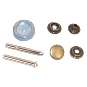
  8. From an aesthetic standpoint I decided to go with black pleather and studs similar to the following picture to close the bracelet.
    0021607_press-stud-kit-antique-brass

Progress
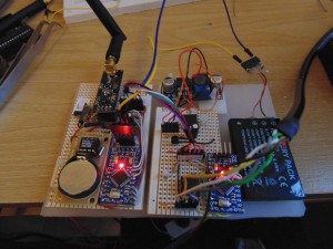
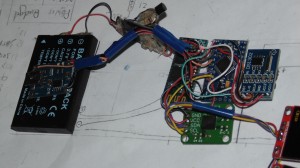
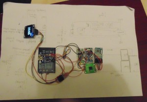
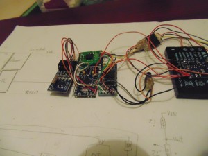
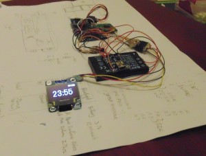
So far I have connected one screen andall of the major components, I have not yet connected buttons and currently the DS1302 still needs it’s pin headers removing to lower it’s height profile. It’s currently still an early prototype so the components are bluetacked to a piece of paper. Sketches are uploaded over Bluetooth serial and using the manual reset button on the Arduino.
From a software standpoint the features currently implemented to some extent, although not necessarily finished are:

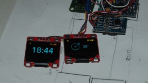
  1. Interfacing with the DS1302 (real time clock) and displaying the time on the screen while using power saving to extend battery life. Battery life in this mode with the screen constantly on is a little over 5 days. This is not feature complete yet though because it does not yet show the date.
  2. Interfacing with the HMC6352 (compass) and displaying a compass on the screen with a numerical heading. This is not yet completely feature complete because the compass requires calibrating, I can however rotate the setup and the compass arrow keeps a constant direction.
  3. Power management and low power mode. I can currently read the voltage of the battery by using the internal Arduino reference voltage of 1.1v and a resistive voltage divider. The raw reading are then passed through an equation which extrapolates the current charge remaining from points on a Li-Ion discahrge curve. I’ve also begun to implement low power such as sleeping the compass module, disabling the bluetooth and putting the Arduino into low power mode.
  4. Some serial communication. It’s currently possible to use binary based commands to get the amount of free memory and set the time for the clock module.

That’s all that’s implemented for now but I’ll be beginning on the casing soon. Below are some pictures of the prototype in it’s current state.

Pictures

DSC00339 DSC00341 DSC00340