Budget Arduino Smartwatch

Once again there’s a new project on the go and possibly my most ambitious thus far, my first experiments into wearable technology. The device in question is a budget smart watch using cheap eBay components in a bracelet format.

In this post I intend to cover the initial designs, requirements, then to describe the components used including reasons for selection and finally describing the initial prototype and implementation thus far.

Inspiration
Hackaday is a website showcasing hacked together projects, sometimes to a more professional level. These projects happen to include various smart watches, and it’s from these I draw my inspiration.

My main source is this, which is a wonderful design, done very well and in a very compact way with a seemingly well built companion app for Android. My other source is this Ardubracelet, which whilst not as aesthetically pleasing adds some interesting design elements, such as capacitive buttons and multiple screens.

Requirements
From these two main projects I decided I wanted something that follows the following vague requirements:

  1. More than one screen. (I decided to use two placed next to each other.)
  2. Capacitive buttons.
  3. Bluetooth. To receive notifications from a phone, provide media controls, access services such as GPS and allow an interface to store more persistent data such as GPS coordinates.
  4. Compass. Extending the features in requirement 3 I want to be able to store GPS coordinates and have an arrow pointing at them. Whilst this is possible with just GPS it doesn’t work quite as well when walking.
  5. Real Time Clock. The primary feature of the bracelet would be to display time, I wanted to be able to do this independently of the phone so Bluetooth is only enabled when necessary to save power.
  6. A good battery life. This means having a large battery, far more so than in similar projects and optimising power usage.
  7. Reasonably aesthetically pleasing and durable.

Parts List
From those requirements I gathered the following parts list, plus some minimal components such as transistors and resistors.

  1. Arduino for the processor. This was a difficult choice after the Teensy 3.1 came out which is a far superior board in a compact form factor. However, compared to an Arduino Pro Mini clone from China which is £1.50 including postage the Teensy 3.1 would cost around £25 including postage. The Arduino Pro Mini also supports power saving modes and is very low power in it’s own rights after removing the power LED and cutting the trace for the voltage regulator. I used the 16Mhz 5v model which is just about officially supported running at 3.7v.
  2. HMC6352 compass module. This is an old 2-axis field sensor. I used this because I happened to have one lying around, it uses <1ma current and supports 3.3v to 5v operation.
  3. Bluetooth serial JY-MCU HC-06 module. This is a cheap Bluetooth serial module from China which it’s sometimes possible to pump 5v into them without them breaking, as is the case with the one I own, but they run down to 3.3v. This modules cost about £5 including postage and draw about 20ma.
  4. DS1302 real time clock. I’m using a DS1302 based module from China that includes a backup battery and some supporting circuitry. These modules can be trickle charged and even without trickle charging keep time for about 10 years. They cost around £3.
  5. Battery. A cheap Li-Ion 1200mAh 3.7v from China  for the Fujifilm NP-60. About £3 with postage.
  6. Charger. A micro USB Li-Ion charger which connects straight to the battery. This costs about £2 with postage.
  7. 0.96″ OLED screens as used in both of the projects references earlier. These things are cheap, great to see in daylight and use relatively little energy for screens.
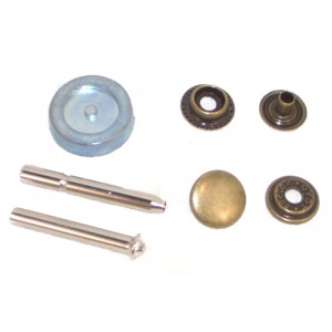
  8. From an aesthetic standpoint I decided to go with black pleather and studs similar to the following picture to close the bracelet.
    0021607_press-stud-kit-antique-brass

Progress
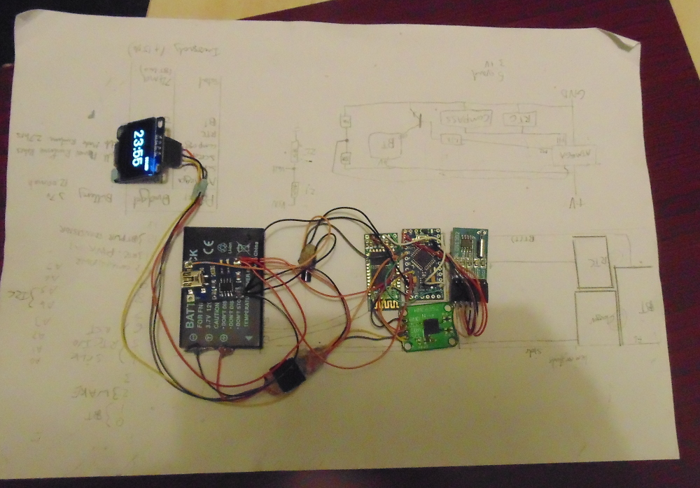
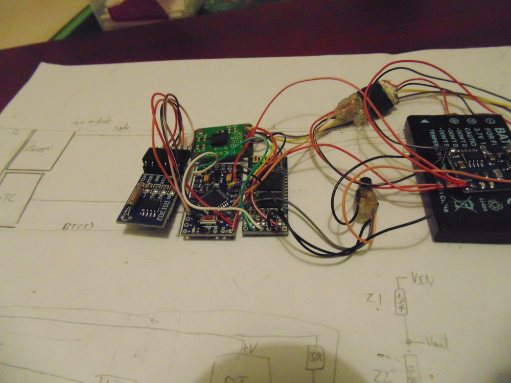
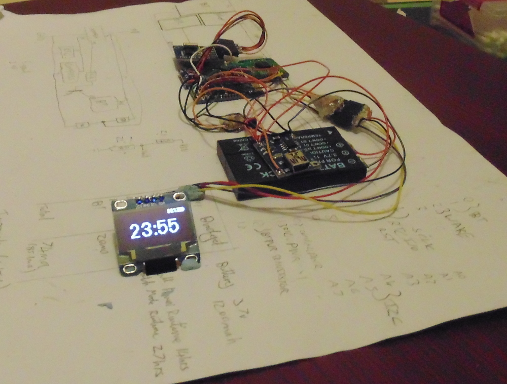
So far I have connected one screen andall of the major components, I have not yet connected buttons and currently the DS1302 still needs it’s pin headers removing to lower it’s height profile. It’s currently still an early prototype so the components are bluetacked to a piece of paper. Sketches are uploaded over Bluetooth serial and using the manual reset button on the Arduino.
From a software standpoint the features currently implemented to some extent, although not necessarily finished are:

  1. Interfacing with the DS1302 (real time clock) and displaying the time on the screen while using power saving to extend battery life. Battery life in this mode with the screen constantly on is a little over 5 days. This is not feature complete yet though because it does not yet show the date.
  2. Interfacing with the HMC6352 (compass) and displaying a compass on the screen with a numerical heading. This is not yet completely feature complete because the compass requires calibrating, I can however rotate the setup and the compass arrow keeps a constant direction.
  3. Power management and low power mode. I can currently read the voltage of the battery by using the internal Arduino reference voltage of 1.1v and a resistive voltage divider. The raw reading are then passed through an equation which extrapolates the current charge remaining from points on a Li-Ion discahrge curve. I’ve also begun to implement low power such as sleeping the compass module, disabling the bluetooth and putting the Arduino into low power mode.
  4. Some serial communication. It’s currently possible to use binary based commands to get the amount of free memory and set the time for the clock module.

That’s all that’s implemented for now but I’ll be beginning on the casing soon. Below are some pictures of the prototype in it’s current state.

Pictures

DSC00339 DSC00341 DSC00340

New Game Updates

Today I found some time to work on my new game. And the next 2 items on the agenda were a better form of player movement and player-world collisions.

Player movement is done in a reasonably common way. A sprite has a velocity and pressing a key will influence the velocity in a direction, such as the right arrow key will set the velocity in the X axis to a positive number in this case. Then a timer loop is run where the time since the last loop is taken into account and the sprites position is altered based on the time that has passed and the sprites velocity.

But by far the more interesting part of todays session was collisions. Collisions in 2D in a game like this are essentially very simple, all that has to be done is to check if the points of the bounding box of the sprite overlap a solid point in the world. The fun part is deciding which parts of the world are solid. I elected to split each tile into 4 sub-tiles, this means that a sprite can enter a tile where only half of the tile may be a solid wall. It would have been a very simple but tedious task to manually assign the values to these sub-collision grids with a small modification to the level editor mentioned in the previous post. But, that would certainly have made level design a lot less fun and increased development time dramatically down the line.

So I took an alternate approach to creating this grid. In my previous post I mentioned that each tile is split into 2 layers, a background layer and a foreground layer. The way that the graphics designer has been designing so far it was safe enough for me to assume that if the tiles background is checked as solid that the whole tile is solid. However, some foreground graphics such as walls and doors only take up half a tile. These foreground images are designed with transparency to allow overlaying on a background image, I was able to re-use this transparency in generating my collision grid because I knew only areas which were opaque were solid. This is nothing new to games design, but it was fun to lightly dabble in image manipulation. Some screen-shots of todays session follow.

This screen-shot doesn't show ant collisions, just to demonstrate the new player sprite and the square in the top right for testing which shows whether the player sprite is currently colliding.
This screen-shot doesn’t show any collisions. It just to demonstrates the new player sprite and the square in the top left for testing which shows whether the player sprite is currently colliding with the world.
This image demonstrates sub-tile collisions. The player sprite was able to enter the tile but not pass into the wall. The red square shows that the player is currently colliding.


New Game Beginnings

This weekend I woke up rather motivated to do something a little fun. So I decided it’s time I try and make a simple game, with a plot. An hour later after a coffee and I’m on the phone to Alex and we’re discussing possible plot lines and have soon created a plot outline and opening scene.

I wanted this to be an exercise in programming as well as game development so I have opted to make me own game engine with a front facing isometric view similar to the Pokemon Gameboy games. I then set out to create a simple level designer and graphical resource manager because I must admit, this isn’t the first time I’ve tried to make a 2D game. The first time was when I was much younger and a major problem was generating content. Although that project was flawed in other ways, this inability to create content destroyed development.

This is a screenshot showing the level designer in use.
The games level designer in use. (Graphics courtesy of Alex)

The above image shows the level designer. It has 3 windows. The window on the left is the resource manager. From here it’s possible to select a resource for placement or add and remove resources. On the right is the main design window where it’s possible to place tiles in 2 levels with a foreground and background image. The window at the top shows attributes of the currently selected tile which is the one within the green box.

Tiles have a very minimal set of attributes solid, foreground and background being mentioned in the previous paragraph. Action and Attribute fields are designed to allow coding of generic tile animations and state changes, for instance action could be “door” and attribute could be “open”. In this case when this tile would be interacted with the game engine could change the state and image of the door to allow it to open and close.

After having a level designer created and some basic resources to use such as a level design and some images I begun working on the game itself. The first screen I created was the menu, shown below in early development.

The games main menu screen.

This screen is interacted with through the arrow keys to choose a menu option and the enter key. Load currently loads a second menu where a save slot can be chosen. Start new at this time loads into a test level with very basic sprite movement to test level rendering as shown below.

Game Level Rendering Test

The screen-shot above shows the level rendered. The center of the screen is always focused on the player sprite which, in this case, is the little dinosaur on the screen.

This is the game after a weekend of development so hopefully it will continue to go well.

Arduino Real Time Clock

Recently I’ve been working an Arduino real time clock with a 4 digit 7 segment display. The real time clock chip is a DS1302

Arduino Clock

In the bottom left is the 4 digit 7 segment display, the bottom right the DS1302 RTC chip and the top right an Arduino Pro Mini. The device is powered over the serial cable which can also be used with a small Java command-line program to synchronize the clock and set an alarm which is currently only implemented in software.

The code for the Arduino and the Java application can be found at this Git Repo.
https://github.com/timstableford/ArduinoRTC