The game I’ve been previously working on has now ground to a halt so I can spend more time playing guitar. So I decided it was time to publish the code on Github since it is in a reasonable state despite lack of documentation.
Today I found some time to work on my new game. And the next 2 items on the agenda were a better form of player movement and player-world collisions.
Player movement is done in a reasonably common way. A sprite has a velocity and pressing a key will influence the velocity in a direction, such as the right arrow key will set the velocity in the X axis to a positive number in this case. Then a timer loop is run where the time since the last loop is taken into account and the sprites position is altered based on the time that has passed and the sprites velocity.
But by far the more interesting part of todays session was collisions. Collisions in 2D in a game like this are essentially very simple, all that has to be done is to check if the points of the bounding box of the sprite overlap a solid point in the world. The fun part is deciding which parts of the world are solid. I elected to split each tile into 4 sub-tiles, this means that a sprite can enter a tile where only half of the tile may be a solid wall. It would have been a very simple but tedious task to manually assign the values to these sub-collision grids with a small modification to the level editor mentioned in the previous post. But, that would certainly have made level design a lot less fun and increased development time dramatically down the line.
So I took an alternate approach to creating this grid. In my previous post I mentioned that each tile is split into 2 layers, a background layer and a foreground layer. The way that the graphics designer has been designing so far it was safe enough for me to assume that if the tiles background is checked as solid that the whole tile is solid. However, some foreground graphics such as walls and doors only take up half a tile. These foreground images are designed with transparency to allow overlaying on a background image, I was able to re-use this transparency in generating my collision grid because I knew only areas which were opaque were solid. This is nothing new to games design, but it was fun to lightly dabble in image manipulation. Some screen-shots of todays session follow.
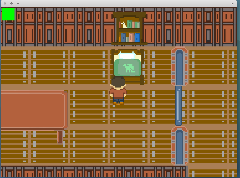
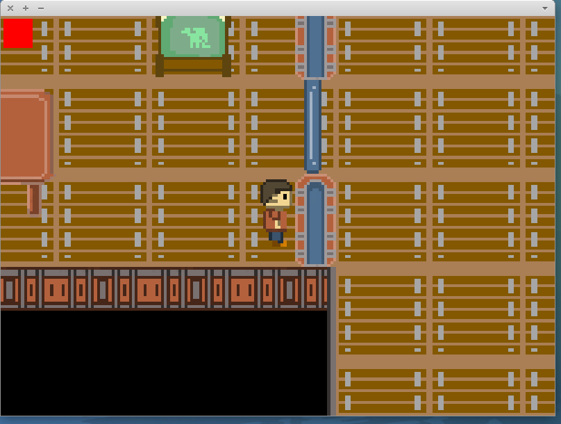
This screen-shot doesn’t show any collisions. It just to demonstrates the new player sprite and the square in the top left for testing which shows whether the player sprite is currently colliding with the world.This image demonstrates sub-tile collisions. The player sprite was able to enter the tile but not pass into the wall. The red square shows that the player is currently colliding.
This weekend I woke up rather motivated to do something a little fun. So I decided it’s time I try and make a simple game, with a plot. An hour later after a coffee and I’m on the phone to Alex and we’re discussing possible plot lines and have soon created a plot outline and opening scene.
I wanted this to be an exercise in programming as well as game development so I have opted to make me own game engine with a front facing isometric view similar to the Pokemon Gameboy games. I then set out to create a simple level designer and graphical resource manager because I must admit, this isn’t the first time I’ve tried to make a 2D game. The first time was when I was much younger and a major problem was generating content. Although that project was flawed in other ways, this inability to create content destroyed development.
The games level designer in use. (Graphics courtesy of Alex)
The above image shows the level designer. It has 3 windows. The window on the left is the resource manager. From here it’s possible to select a resource for placement or add and remove resources. On the right is the main design window where it’s possible to place tiles in 2 levels with a foreground and background image. The window at the top shows attributes of the currently selected tile which is the one within the green box.
Tiles have a very minimal set of attributes solid, foreground and background being mentioned in the previous paragraph. Action and Attribute fields are designed to allow coding of generic tile animations and state changes, for instance action could be “door” and attribute could be “open”. In this case when this tile would be interacted with the game engine could change the state and image of the door to allow it to open and close.
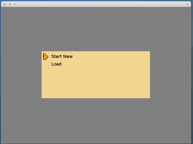
After having a level designer created and some basic resources to use such as a level design and some images I begun working on the game itself. The first screen I created was the menu, shown below in early development.
The games main menu screen.
This screen is interacted with through the arrow keys to choose a menu option and the enter key. Load currently loads a second menu where a save slot can be chosen. Start new at this time loads into a test level with very basic sprite movement to test level rendering as shown below.
The screen-shot above shows the level rendered. The center of the screen is always focused on the player sprite which, in this case, is the little dinosaur on the screen.
This is the game after a weekend of development so hopefully it will continue to go well.
Recently I’ve been working an Arduino real time clock with a 4 digit 7 segment display. The real time clock chip is a DS1302
In the bottom left is the 4 digit 7 segment display, the bottom right the DS1302 RTC chip and the top right an Arduino Pro Mini. The device is powered over the serial cable which can also be used with a small Java command-line program to synchronize the clock and set an alarm which is currently only implemented in software.
I’ve recently found time to work on my Pi Car and it is now in a mostly working state with one thing I haven’t quite found yet.
It now has a webcam mounted on it and acts as a wireless access point with DHCP server. I went down this route for portability. This meant that I could easily create an Android App that controlled the movement of the car. This currently looks very similar to the application for my Bluetooth car (seen here) except that it runs on Android and connects over Wifi.
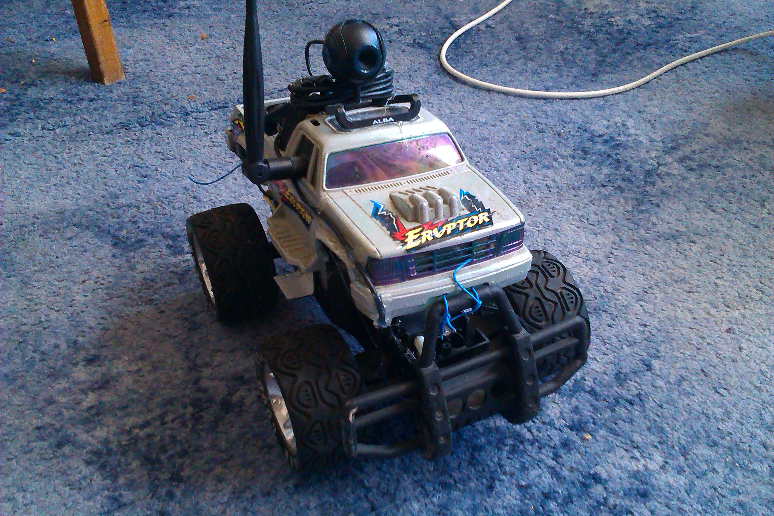
An outside view of my Pi Car with mounted webcam
As you can see from the picture above the car now has a webcam mounted to it’s top, this is currently streamed to a laptop using ffmpeg but I have future plans to stream to the Android App.
The Raspberry Pi primarily acts as a Wifi shield for an Arduino in the car which interfaces with the motors, as well as streaming the webcam.
This shows the inside of the car, the board in the center is a Raspberry Pi, the one in the cabin of the car the Wifi.